Routing
Using a Collar
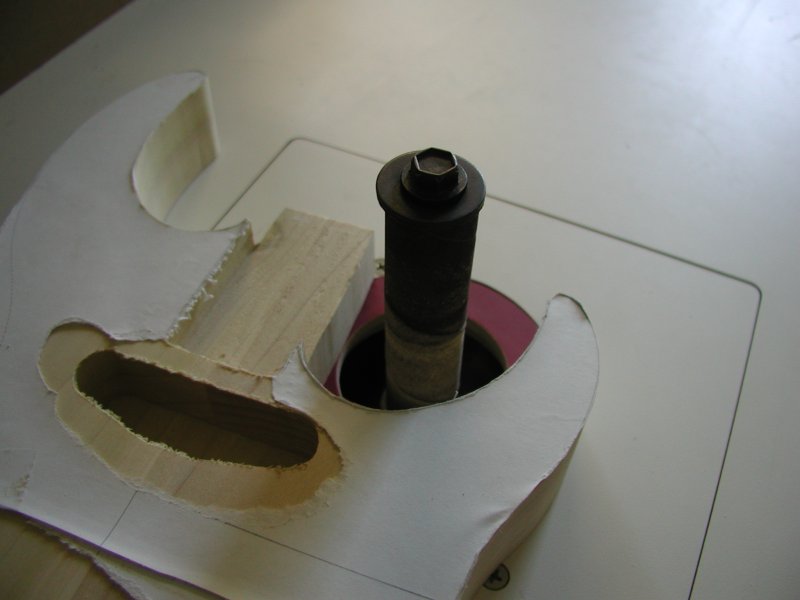
Instead of the typical top-bearing router bits that are sold specifically for routing cavities, I used a 1/4 inch spiral cut bit with a 7/16 inch diameter collar to guide the router. Using the collar meant I had to offset the templates to accommodate the difference between the bit and the collar. This wasnt too much of a problem for me since I could just use the offset tool in my CAD program to create the templates. (Note: If you use the templates included in the CAD file on the first page, keep in mind that you will need to use an equivalent collar setup to route the cavities to the correct size.)
Making the Templates
I made two templates for this EOM. One was made for the top cavities including the two pickup cavities and the neck pocket. The other was used to route the control cavity cover recess and control cavity on the back of the instrument. Both templates were made out of 1/4 inch mdf since it is easy to file and doesnt warp. I made the templates extra large to provide plenty of support for the router base and so they would clamp or screw on to the blank easily and securely. With a paper template glued down to each of the two templates, I started the cutouts with a large hole. I used a jigsaw to rough cut the openings then cleaned them up with a wood file and the spindle sander. I routed a quick test on a scrap piece of wood to see how they finished cavity would look and refined the shape accordingly.
Attaching the Top Template
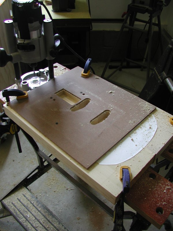
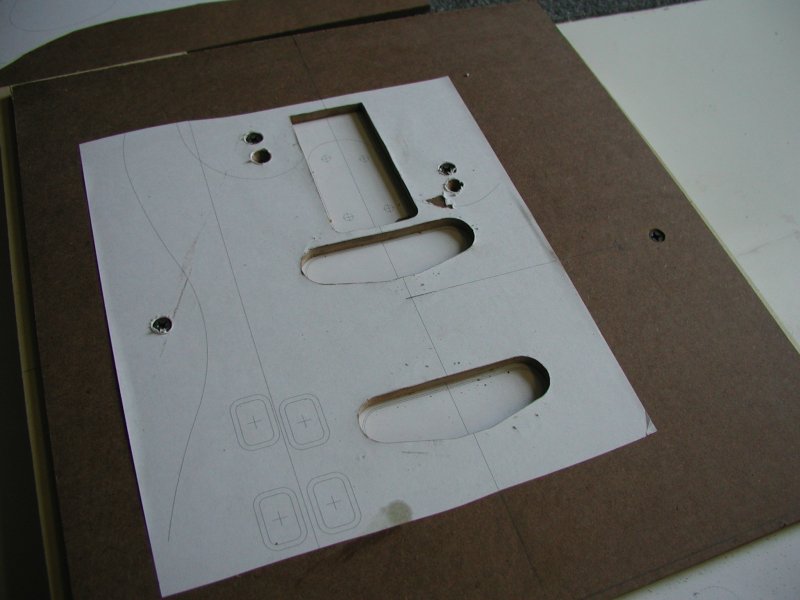 To attach the top template I lined it up with the paper template on the top of the body blank and fastened it in place with screws making sure that the screws would avoid the body. With four screws all counter sunk into the template (one between each horn and one at the waist on either side) the template was very secure without interfering with the router. All I had to do was secure the entire assembly to a solid table so it wouldnt move out from under me while routing and I was ready for the first major operation of the build.
Routing the Top Cavities
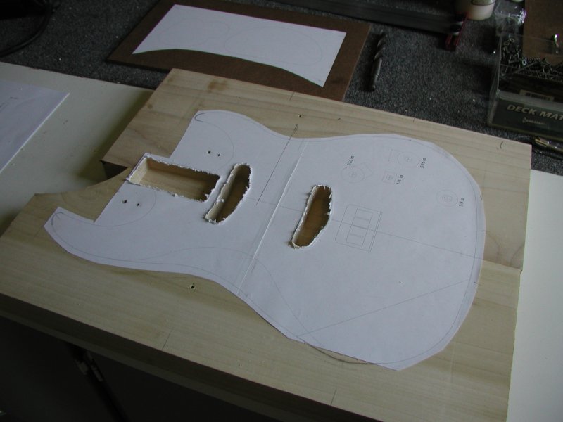
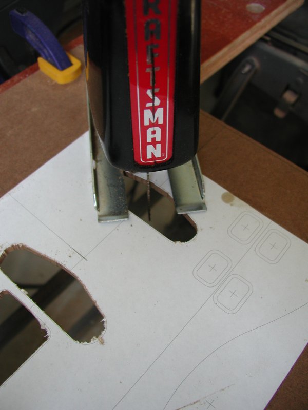
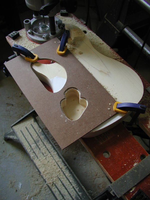
I routed the cavities one at a time, taking them down to their final depth in about 1/4 inch passes. I accidentally went too far on the pickup cavities due to the depth set screw slipping. This wasnt a big deal on these cavities, but allowed me figure out what I was doing wrong in time to route the more critical neck pocket correctly. The pickup cavities should be about 7/8 inches deep, but the best depth may vary depending on how high the pickup needs to project above the top of the body and the hardware your using. The neck pocket should be as close to 5/8 inches deep as possible.
Drilling for the Electronics
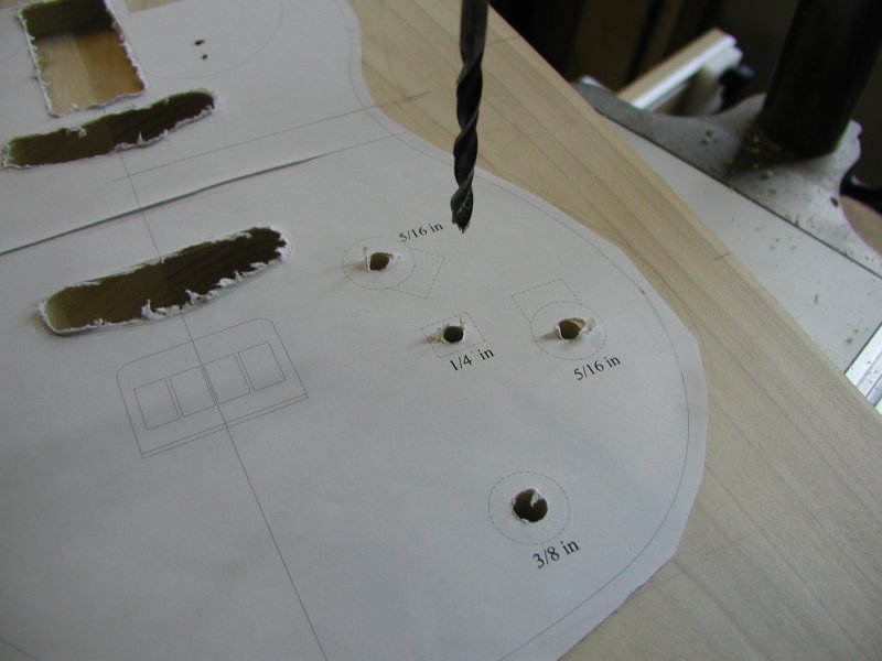 Before routing the rear cavities, I went ahead and drilled holes through the top for the electric components to avoid tearout.
Cutting the Top Profile
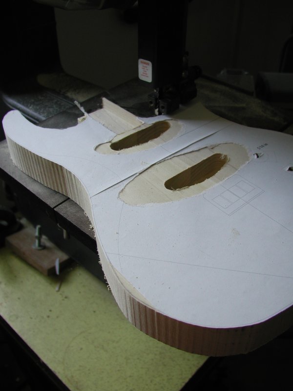
At this point, I cut out the top profile with a bandsaw. I used a combination of a disc and spindle sander to smooth the edges and bring them down to size. I did this before routing the rear template so I could position the cavity more accurately in relation to the template on the top side of the body.
Routing the Electronics Cavity
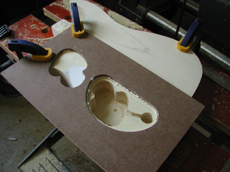
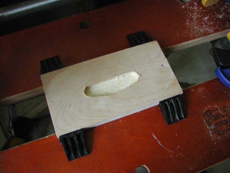
I aligned a new paper template for the electronics cavity using the edge and the center line of the body as guides. I had to clamp the template down since there wasnt any wood left outside the body to screw into. The clamps I used interfered with the router in one area, but with some readjusting allowed for an accurate result overall. I routed the inner pattern of the cavity first in 1/4 inch increments leaving a 1/4 inch of material for the top surface. I also drilled a separate 7/8 inch hole for the output jack to the same depth. I routed the cover recess to about 1/8 inch deep to fit the plastic cavity cover stock. Its important do this routing carefully so the cavity cover fits flush with the back surface of the body.