Wiring
Shielding
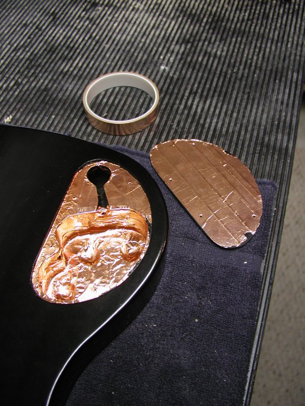 I shielded the cavity and the underside of the cavity cover using 3/4 inch wide copper tape with a conductive adhesive to create a continuous barrier against hum and noise. This ended up being easier that I though it would be despite the small area I had to work in and the odd shape to be covered.
To shield the cavity, I first taped the top surface where the cavity cover would rest so it would make a solid connection all the way around with the shielded underside of the cavity cover. I also cut slits in that tape and folded it over the edge for continuous contact with the tape on the sides of the cavity. I added tape all around the vertical surfaces overlapping the edges and ends of the tape with each other. I placed the shielding on the bottom of the cavity in rows of the bottom surface again overlapping and covering as best as I possibly could over the recesses that the electronics will fit into. After I finished shielding the bottom, I realized I really should have put the copper tape on the sides last for a neater looking job since the sides are very easy to add cleanly.
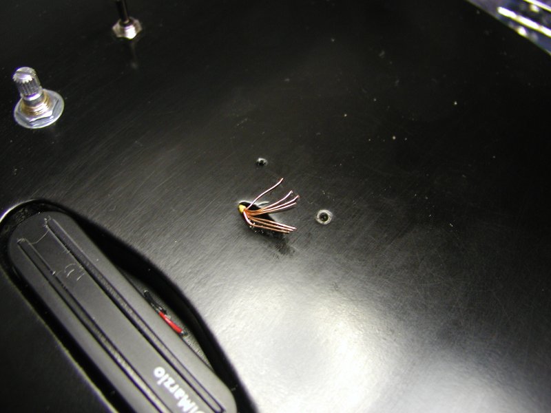
I did not cover the separate output jack part of the cavity. This section isnt usually covered when it is on the side of a guitar since it is too small, so I didn't shield this instrument either. Instead I shielded the wires running to output jack. I used copper tape, but it would probably be a better idea to use a shielded two conductor wire instead.
Wiring Diagram
I worked off of a standard wiring diagram that uses one potentiometer each for volume and tone and a three way selector switch with two pickups. There is a large variety of diagrams available online so it should be possible to find something close to what you want with a search. I had to modify the diagram I found to include four conductor pickups and the three way switch I bought which isnt typically used for pickup selection. I was able to figure out the wiring using a combination of the pickups instructions, the wiring diagram I found and an ohmmeter which I used to test how the switch was wired internally. (It was not wired how I had originally guessed: The ohmmeter definitely saved me from rewiring everything a few times.)
Wiring
Wiring was done in a few stages for my own sanity since space gets very scarce by the time all the wires are installed. It is also especially helpful to work in an organized fashion when trying to make sure wires arent going to short to ground and that everything is connected where it should be.
Ground and Between Components
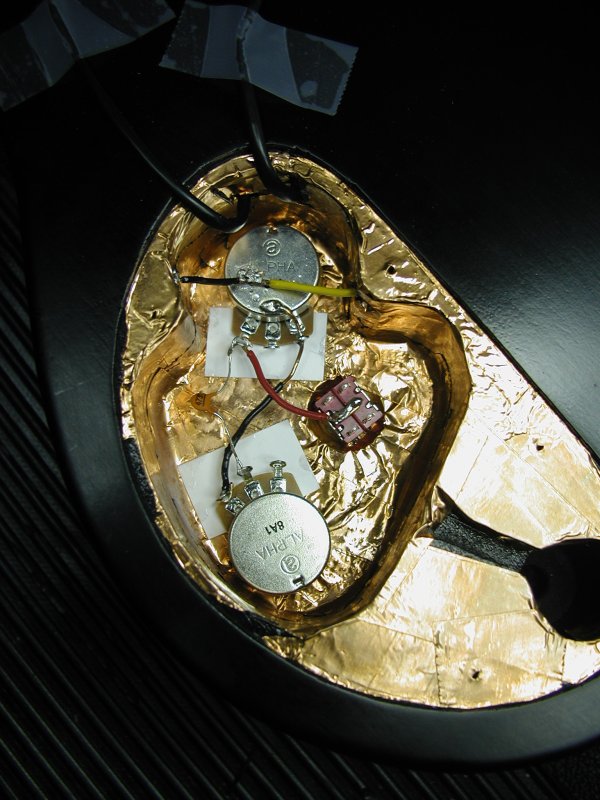
I started by gluing down pieces of card stock under the connections of the potentometers with super glue to prevent these connections from grounding to the shielding. With all of the components in place and prepped, I soldered the ground wire directly onto the shielding and connected it to the back of the volume pot. I also soldered the wire that connects to the bridge to the back of the volume pot. I wired the various connections between components next. This got these connections out of the way before bringing all of the wires from outside into the cramped compartment.
External Components


Testing
The ohmmeter was very helpful for testing how components work and to check connections so I knew the circuit was doing what I wanted it to. One part I was very curious to test was the shielding. It did conduct effectively from one end to other of the cavity and to the ground of the electronics system through the soldered connection I made. This is what it is supposed to do, but I was still a little amazed that it all conducted so well across all those different pieces of tape. I was also somewhat amazed that the entire system all worked as expected on the first try without revisions considering all the improvising I did.